
Tuesday 18 December 2018
Thursday 13 December 2018
New Rear Springs - Before
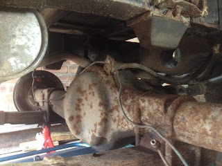
I've got some new rear parabolic leaf springs from GB Springs ready to fit, and will also be fitting new check straps and cleaning up the axle and chassis and shocks on the back. If I'm lucky I'll get this done over the Christmas holidays ready to move onto new brake pipes in January.
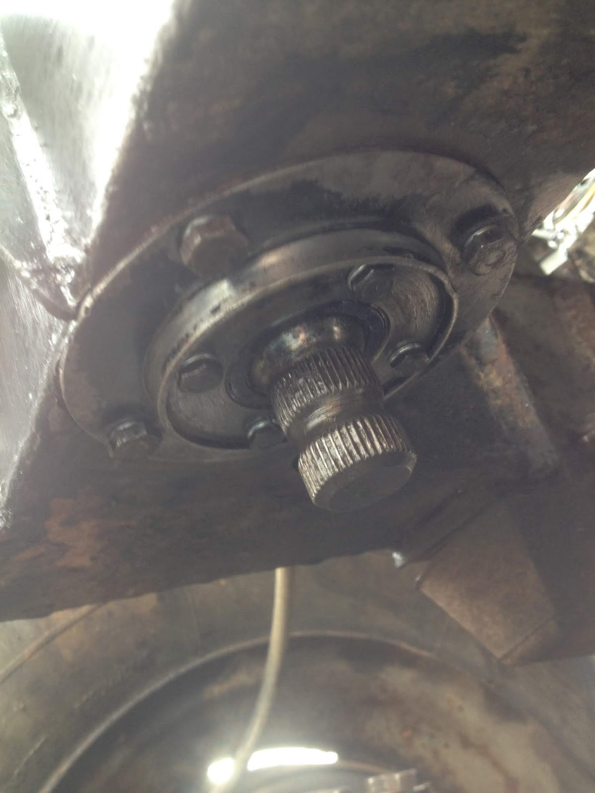
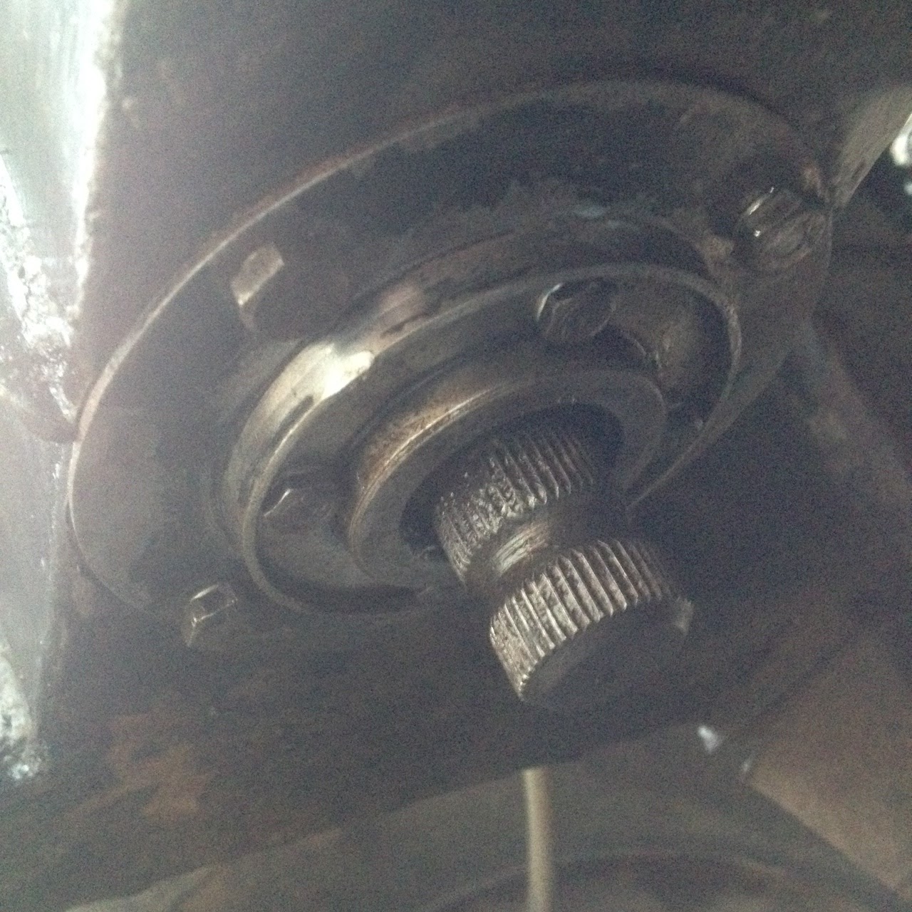
Some 'before' shots..


This time I had the sense (and familiarity with the grinder!) to cut the old u-bolts off. Much quicker!
Some 'before' shots..


This time I had the sense (and familiarity with the grinder!) to cut the old u-bolts off. Much quicker!
New Fuel Tank
With both fuel tank outriggers replaced I was able to fit the new fuel tank recently. This went smoothly for me, but these reproduction tanks have a slight issue in that the filler neck is in a slightly different position. Because I was replacing both outriggers I was able to position it as I needed, but others have had to cut their tub about a bit to get the filler neck in position. Not good, and it's been going on for a while with no sign of the manufacturer of these tanks wanting or trying to fix the issue.
The sender unit was so corroded the float arm started bending before it would hinge. The gauze filter on the bottom of the elbow pipe was gone completely. I ordered OEM versions of both and fit them as new.
The new tank is on the vehicle now. I'm missing a photo of it in place at the moment, but it looks good.. :)
 |
| Spot the difference.. |
 |
| Old fittings needed replacing |
Tuesday 4 December 2018
Front Fuel Tank Outrigger
There was hardly any wind today so I jumped on the last of welding for the year. Front fuel tank outrigger in place and painted. With the rail already repaired it was a straightforward couple of hours.

Next job is to fit the new fuel tank and hoses, and then finish off cleaning up and painting the chassis here under the seat base.
When that's all squared away and tidy I'll put her on axle stands and start on the rear suspension and axle and chassis cleanup. I need to order some new springs for the rear as they're too far gone for a simple refurb. Also need new check straps as they're not even there anymore. The strip light in the garage should make the evenings in the garage more doable this winter.
Saturday 17 November 2018
O/S Bulkhead Outrigger
The old front fuel tank outrigger was never welded along the top, and since it was welded along the bottom moisture had run down behind it against the chassis rail over time and sat there - and rot through the rail.
When I cut rot out from behind it I looked at the driver's bulkhead outrigger and knew it would be the same since there was an enormous pile of bad weld on its top edge that had not penetrated well and so popped away from the chassis rail under stress. It was also not level, being too low beneath the door pillar.
So I cut them both off at the same time, along with about 18" of rail..
Behind the rail it was ok. The floor and sides all rang well under the hammer. I re-taped the wiring loom with insulation tape, ground out and drill-brushed the floor, top and sides of the rail inside, and painted it all out with Chassis-in-one.
This time I started with a slightly larger repair section and ground down to fit. This went much better than before. As it was 18" long I tacked the points that were flush with the adjacent metal and then used the point of a chisel to slightly lift over sections into line before tacking. Then I welded all around the section and flushed it off and was happy I could run my hand along the rail without any obvious contours. I probably spend too much time on this kind of thing.
When I offered up the new outrigger the fun began. It didn't fit. I measured it against the new one on the N/S and it was the same. I got the spirit level out and checked various points on the chassis, and the driveway.. after a while I turned the radio off. I do that when I get worried. :)
When I cut rot out from behind it I looked at the driver's bulkhead outrigger and knew it would be the same since there was an enormous pile of bad weld on its top edge that had not penetrated well and so popped away from the chassis rail under stress. It was also not level, being too low beneath the door pillar.
So I cut them both off at the same time, along with about 18" of rail..
 |
| Old driver's bulkhead outrigger |
 |
| Before. I forgot to photo 'After' I'd cleaned it up and painted inside.. |
 |
| 18" chassis rail repair section ready for tacking |
I couldn't work out was wrong, and then I noticed the door pillar's foot on this side, that the outrigger bolt passes through, was not running parallel beneath the edge of the floorwell like on the other side. I know the pillar needs replacing as it's badly corroded, but I think it may also have taken a hit at some point as there's lots of other evidence for the previous owner using it for leisure off-roading.
I couldn't weld the new outrigger on to fit the damaged pillar because when I replaced the pillar the outrigger would then be wrong. I had to the weld the outrigger on correctly, square and flush with the top of the chassis rail, as I'd done on the passenger side, and bring the damaged pillar into line.
To cut a long story short, it took two hours, two jacks, some bits of wood, an axle stand, and a lot of swearing, but eventually I got the outrigger square on the rail with its bolt running through the pillar's foot - and quickly tacked it into place. Then I slowly removed the shims I had holding everything square, one-by-one, and slowly welded the outrigger on as I exposed more and more edges of its back plate.
Compare the pillar foot running straight underneath the floor well with the angle it runs at in the photo of the old one above..
This solves a mystery and a problem. The old outrigger was not level. I suspect it was welded on after the door pillar sagged or was hit, which is why it ran down toward the pillar's slopey foot instead of sitting level. This also explains the huge pile of bad weld on its top edge - because it was running downward off the rail there was a huge gap at the top - too much to fill with weld, but that didn't stop them trying.
One more outrigger done, and the bulkhead should be sitting a bit better now too. I've wondered why my driver's door didn't fit very well.. :)
Compare the pillar foot running straight underneath the floor well with the angle it runs at in the photo of the old one above..
 |
| The result is square and straight, unlike the previous one |
One more outrigger done, and the bulkhead should be sitting a bit better now too. I've wondered why my driver's door didn't fit very well.. :)
Thursday 1 November 2018
Rear Fuel Tank Outrigger
 |
The new outrigger didn't come with a bracket to fix it to the underside of the tub, so I cut the old one off and welded it to the new outrigger to re-use it. The previous post talked about how I 'moved' one of the holes that had been drilled offset. The hole in the tub just needed widening a touch to take the bolt in the new position, which was not a big deal as the tub behind the bracket was already quite badly corroded and would need reinforcing anyway.

This is not a load bearing mounting point, it's just to give the tub some extra rigidity by connecting it to the chassis, but I decided to cut some aluminium plates to reinforce the section anyway.

The chassis rail behind the outrigger needed a repair section welding in. While I had the rail open I was able to check the loom. This vehicle has had a new rear quarter-chassis fitted at some point, and I think while that was done the loom lost its binding somehow. I re-taped these wires up with insulation tape and pushed them to the back of the rail away from where I'd be welding.

Here is the repaired chassis rail with some weld-through primer applied, and the bracket (before I 'moved' the right-hand hole), and aluminium plates in position. There's another plate on the other side, and I have some rivets coming in the post so when they arrive I will put a rivet in either side of the bracket to hold the tub and plates together and take the stress off the original corroded section.

Next, I clamped the outrigger to the chassis rail and jacked the new fuel tank up into position so I could tack weld the outrigger to the bracket in the correct position. Then I removed it all and welded the bracket to the outrigger in the garage where I could move to get a bead all the way around it.

With all that done it was reasonably straightforward to weld the outrigger on. Here you can see the modified bracket with stainless steel fixings that should not react with the aluminium plates or tub where they go through.
I had to cut about 3-4mm off the top of the outrigger's back plate, and a bit more, at an angle, off the bottom because it was slightly deeper than the chassis rail. Making these cuts meant I could get nice flush beads along the top and bottom.
There was some more awkward welding than with the bulkhead outrigger. For the front bead, under the driver's seat, I had to sit up inside the seat base where the fuel tank would normally be and weld left-handed. I wasn't looking forward to the top bead, as there's not much clearance between the chassis rail and floor, but that actually went quite well - watching from one side of the outrigger while controlling the gun from the other actually worked perfectly.
I need to bolt the sill stay back on and rivet those plates, and then the next job is the front fuel tank outrigger. I wasn't going to replace that one, but as the new fuel tank has a slightly different filler neck, I've got to move that front outrigger back about an inch to get everything lined up, and so I may as well fit a new one.
So far so good, and the worst welding on the vehicle is still not mine! ;)
How to Move a Hole
I wanted to re-use the bracket from the old rear fuel tank outrigger that connects to the underside of the rear tub. But the holes in the bracket were not very even, so I needed to move one of them..
I read recently how you can use something like copper as a backing plate to fill a hole in mild steel, since it does not take the arc, and so I thought I'd try it.
 |
| The old bracket on the new outrigger.. holes not my own! |
 |
| Copper pipe hammered flat |
 |
| Clean hole to fill and clamp copper beneath |
 |
| The copper refuses the arc, lift away when done.. |
 |
| ..and tidy up |
Monday 8 October 2018
First Weld - N/S Bulkhead Outrigger
I chose this is as my first weld job as the outrigger was so completely shot, almost any result would be an improvement!
I had a practice day in the garage first to figure out some settings for 2mm steel and to practice cutting, grinding, working with rustier metal, setting the gas flow right, and so on. I ended up making a weld box for my weld bits. Not flashy but useful actually!

Here's what I was starting with - shot to bits!:

The bulkhead bolt came out with some heat and hammer, it was very badly corroded, almost 2mm narrower at one point.


Starting to offer up the new outrigger. The new bulkhead bolt is also slotted into place to aid alignment:


After tacking top and bottom, I was able to get up the other side in one weld:

After cleaning up I gave it its first coat of Chassis-in-One:


Repairing the chassis rail was the hardest part, but not difficult or technical, just time consuming. Once that was done the outrigger was straightforward. Next job is the rear fuel tank outrigger.
I had a practice day in the garage first to figure out some settings for 2mm steel and to practice cutting, grinding, working with rustier metal, setting the gas flow right, and so on. I ended up making a weld box for my weld bits. Not flashy but useful actually!
 |
| Starting with rust.. |


The bulkhead bolt came out with some heat and hammer, it was very badly corroded, almost 2mm narrower at one point.

Behind the outrigger the rail was rotten so that needed repairing first:

I cut out 1" wider than the rot:

In future I'll be more careful to under cut and grind to fit, rather than over cut and have to weld with a gap. Once I'd tweaked my wire speed up (amps) and voltage down to compensate and avoid blowing through, I was able to work with the gap by "laddering" up both sides and then doing a vertical weld on each side. The result was lumpy..

but smoothed off well, as intended.

Starting to offer up the new outrigger. The new bulkhead bolt is also slotted into place to aid alignment:

On the front side, because there was a crossmember directly behind, I used a piece of 3mm plate to press the middle of the seam good and tight. I welded up to the plate, and from above it to the top, and then when I removed the clamp what was left to weld was sitting tight to the chassis rail:

After tacking top and bottom, I was able to get up the other side in one weld:

After cleaning up I gave it its first coat of Chassis-in-One:


Thursday 27 September 2018
Steering Relay Rebuild Guide
I am having "fun" trying to fill the steering relay with oil.
I still have some ideas left to try and will post what worked in the end when and if I'm successful.
For now, I came across this guide to stripping and rebuilding the relay and wanted to share it and keep a link to it for later should I ever need it:
http://forums.roversnorth.com/showthread.php?16554-Steering-Relay-Rebuild-Guide
Sunday 16 September 2018
Steering Link and Relay (2)
I have fit the new steering link, which was straightforward, and I've fit new gaskets and oil seals in the top and bottom of the steering relay, which was somewhat more interesting!
On the underside, the flange plate I removed appeared to be one piece, and to contain the lower relay's oil seal. After refitting this it struck me as so wrong to have the seal on the outside (i.e. underside) that I couldn't think about much else for a couple of days. The 2/2A workshop manual and parts catalogue didn't help much either, in fact they even showed the seal on the outside. I couldn't accept this though. To me, it looked like something should retain the oil seal up against the bottom of the relay.
Eventually I realised the flange plate was in fact two parts, and someone had inserted the middle part upside down some years ago. Weather and corrosion had then fused them together. I managed to separate them with a hammer and screwdriver, clean them up, and get the lower seal fitted the right way up and now concealed and retained in place. This also meant the lower few mm of the relay shaft was no longer exposed.. something that had led to it getting a little corroded where the lower seal runs against it.
The top seal is on the outside against the base of the upper relay lever, and there's no similar way to reverse the piece it's contained by. I can accept this though, since it's at the top, and not the way the oil will leak out under gravity.

The relay was completely empty when I went to drain it. I scraped most of the old oil from underneath the relay and off the lower lever.. evidence of how poorly that outside seal was performing in the end (it was in pieces when I picked it out).
So.. that's new gaskets and seals on the relay, and new bolts for that upper housing. I'm waiting for a hand-pumped oil can with small flexible hose to be delivered before I can top the relay up with oil. The filler hole is about 6mm!
I also changed the steering box oil today, and replaced the painted battery cage and air filter, along with new rubber pads for the battery tray.

This completes all the steering work I should need for an MOT.
The next job is to make a start on the welding.
On the underside, the flange plate I removed appeared to be one piece, and to contain the lower relay's oil seal. After refitting this it struck me as so wrong to have the seal on the outside (i.e. underside) that I couldn't think about much else for a couple of days. The 2/2A workshop manual and parts catalogue didn't help much either, in fact they even showed the seal on the outside. I couldn't accept this though. To me, it looked like something should retain the oil seal up against the bottom of the relay.
Eventually I realised the flange plate was in fact two parts, and someone had inserted the middle part upside down some years ago. Weather and corrosion had then fused them together. I managed to separate them with a hammer and screwdriver, clean them up, and get the lower seal fitted the right way up and now concealed and retained in place. This also meant the lower few mm of the relay shaft was no longer exposed.. something that had led to it getting a little corroded where the lower seal runs against it.
 |
| Refit as I found it with the seal and end of the relay shaft exposed.. and I couldn't sleep! |
 |
| A-ha! Not one, but two pieces.. flipping the middle around.. |
 |
| And following the brainwave.. with the lower seal and shaft now enclosed. |
The top seal is on the outside against the base of the upper relay lever, and there's no similar way to reverse the piece it's contained by. I can accept this though, since it's at the top, and not the way the oil will leak out under gravity.

The relay was completely empty when I went to drain it. I scraped most of the old oil from underneath the relay and off the lower lever.. evidence of how poorly that outside seal was performing in the end (it was in pieces when I picked it out).
So.. that's new gaskets and seals on the relay, and new bolts for that upper housing. I'm waiting for a hand-pumped oil can with small flexible hose to be delivered before I can top the relay up with oil. The filler hole is about 6mm!
I also changed the steering box oil today, and replaced the painted battery cage and air filter, along with new rubber pads for the battery tray.

This completes all the steering work I should need for an MOT.
The next job is to make a start on the welding.
Monday 3 September 2018
Steering Link and Relay (1)
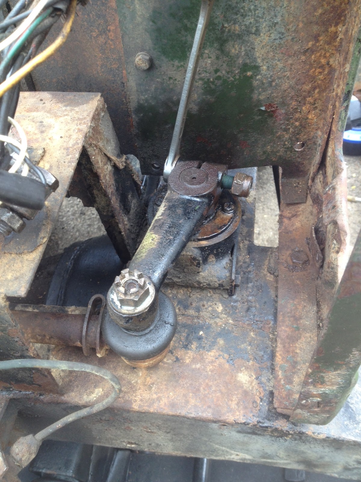
With the battery and air filter cage off my attention was drawn to the condition of the steering link assembly that joins the steering box drop arm to the top of the steering relay in the front crossmember.
The steering link is a 22" tube with a ball joint each end, just like the drag link and track rod underneath. Closer inspection revealed the balljoints were at least dried out, if not worse, and the tubing had seen better days. With the other steering components now renewed, and wanting to clean and paint the front chassis as far back as the front outriggers, I decided it was time to remove this steering link and refurb or replace it.
The upper relay lever sits on a splined shaft, keyed slightly by a pinch bolt that has to be completely removed. The pinch gap can then be opened out with a screwdriver and the lever levered up and off. (You can't get a hammer to this as the chassis is immediately beneath it. I used a balljoint splitter that a friend had widened out with an angle grinder - this turned out to be a perfect fit.)

The drop arm is harder to remove. It's also on a splined shaft (the steering box rocker shaft), and is tight up against a brake pipe union which makes getting even a small 2-arm puller on it very difficult. There's a custom Leyland tool that is designed to fit (#600000), now made by Laser and sold for £35, but as it turned out, I didn't need to remove it.

With the upper relay lever off, you can pull the steering link further towards the front of the vehicle, which pulls the drop arm with it far enough to remove the ball joint on the front side of the steering box mounting bracket. Short version: you only have to take the upper relay lever off, which is easy.
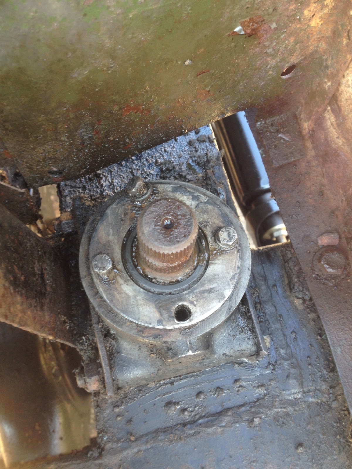
I could now see one bolt was missing from the upper relay housing, exposing the inside to the weather, and another was bent in place(!). I carefully, and luckily, extracted the bent bolt without breaking it.
It looks like this top plate was fit very slightly off centre to the bolt holes, so when this third bolt was wound in it seized and started to cross-thread, but he continued winding until it stopped completely, and then.. he decided to leave it. And I don't know what happened to the 4th bolt. I am hoping when I remove this plate to replace the seal and gasket beneath it, when I go to refit it, I don't find the thread damaged on that side.
I've ordered a new steering link assembly inc. balljoints, plus new bolts, seals, and gaskets for the steering relay, top and bottom. Next job will be get all that fit and the relay topped up with oil again.
The steering link is a 22" tube with a ball joint each end, just like the drag link and track rod underneath. Closer inspection revealed the balljoints were at least dried out, if not worse, and the tubing had seen better days. With the other steering components now renewed, and wanting to clean and paint the front chassis as far back as the front outriggers, I decided it was time to remove this steering link and refurb or replace it.
The upper relay lever sits on a splined shaft, keyed slightly by a pinch bolt that has to be completely removed. The pinch gap can then be opened out with a screwdriver and the lever levered up and off. (You can't get a hammer to this as the chassis is immediately beneath it. I used a balljoint splitter that a friend had widened out with an angle grinder - this turned out to be a perfect fit.)

With the upper relay lever off, you can pull the steering link further towards the front of the vehicle, which pulls the drop arm with it far enough to remove the ball joint on the front side of the steering box mounting bracket. Short version: you only have to take the upper relay lever off, which is easy.
It looks like this top plate was fit very slightly off centre to the bolt holes, so when this third bolt was wound in it seized and started to cross-thread, but he continued winding until it stopped completely, and then.. he decided to leave it. And I don't know what happened to the 4th bolt. I am hoping when I remove this plate to replace the seal and gasket beneath it, when I go to refit it, I don't find the thread damaged on that side.
 |
| The more things like this I find, the more looking I feel like doing.. |
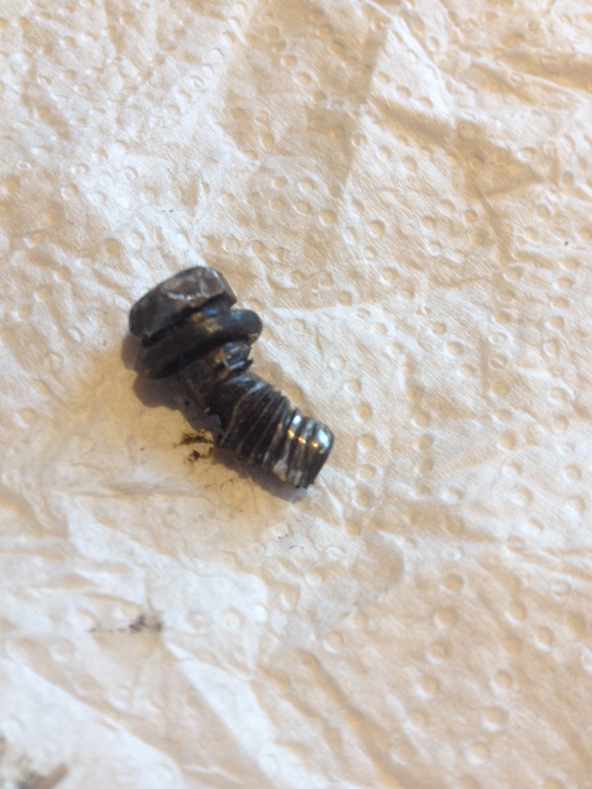 |
| I was lucky to get this out in one piece.. |
Thursday 30 August 2018
2017-2018 - Year 1 Progress Report
With the kitchen mostly finished I'm finding some time for the Land Rover again, and as it's been a year since I brought it home now is a good time to review the progress I've made over the first year:
I hope to be welding by October, and when the bad weather puts that off I aim to progress the rear suspension which will need new springs and so should go a lot quicker than the front.
Considering I didn't know what a differential was when I started, I'm quite pleased with progress so far and dreams of a preliminary MOT before next summer are very much alive.
(Estimated 75 hours effort so far.)
- Brakes - new shoes/cylinders/drums all round
- Hubs - new wheel bearings where needed, hub nuts, lock/key washers, oil seals, drive flange gaskets, stub axle lands, fixings/tabs for backing plates
- Steering - swivel hub refurb'd both sides (new seals, retainers, gaskets, fixings, shims etc.), new track rod, drag link, fit steering damper, fit missing stop plate and jack stop
- Engine/Other - new oil to engine, air filter, and both diffs, new oil filter, cleaned sump and fit with new gasket, stripped and checked oil pump
- Front Suspension - refurb'd front springs (separate leaves, clean and paint), new u-bolts, chassis and spring bushes, shackle pins, refurb'd shocks (new rubbers, fixings, paint etc.)
- Did a welding course and bought a welder (!)
I hope to be welding by October, and when the bad weather puts that off I aim to progress the rear suspension which will need new springs and so should go a lot quicker than the front.
Considering I didn't know what a differential was when I started, I'm quite pleased with progress so far and dreams of a preliminary MOT before next summer are very much alive.
(Estimated 75 hours effort so far.)
Saturday 23 June 2018

Friday 22 June 2018
Sump, Steering, Oil
I had a brief respite from work and kitchen fitting today and made some progress on the Land Rover.
First, I fit the correct, fully-threaded, track rod ends I needed to bring the steering rod and drag link down to the correct proportions. This fixed the toe-out I had on the wheels. I'll get the tracking done optically when I take her for an MOT in the spring.
I also refit the oil pump with fresh locking tabs, fit the cleaned up sump with a new gasket (with RTV silicone), and put a new gasket behind the oil filter housing. Then I filled her up with fresh engine oil and changed the oil in both diffs.
The very next job is to start on the welding, so now I really need to finish that kitchen.. :)
Sunday 20 May 2018
Springs, Shocks, Steering, Damper, Oil Filter, Sump(!)
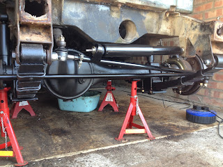
This weekend I managed to get the front springs, shock absorbers, new steering rods, track rod ends, and steering damper fitted. Those dumb irons are really spoiling the view now..
The main steering rod is too long. I ordered as best I could by vehicle and year but the rod itself is longer than the distance the workshop manual specifies to set between balljoint centres. So, she currently has a very large toe-out, but it should not be hard to rectify.
I also fit a new oil filter, and gave the housing a good "clean" while I was there, (as in"Land Rover clean", as in "you should have seen it before I cleaned it..")..

..and stripped the old gasket off the sump and gave that a good clean too.

Next time I get an hour I'll fit the sump back on with a new gasket and some RTV silicone, fill her with new oil.. and start welding!
Oh dear. Wait a minute.. I have to fit our new kitchen first! :O)
Subscribe to:
Posts (Atom)